


updated 08-02-2014
from Tesla’s Flying Machine, page 1
Tesla’s Flying Machine
Page 2
“Tesla’s Flying Stove”
“Not the airplane, the flying machine,” responded Dr. Tesla.

A few weeks later, I traded these motors for 10,000 rpm 1/5hp motors.

Sept.12th, 1992
Second Tesla Space Drive Design
Since nothing is said about weight being an issue, my second
(all steel) frame was built to be rigid, not light-weight.

it was right after this that I figured out the speed
requirement and the variables that affect it
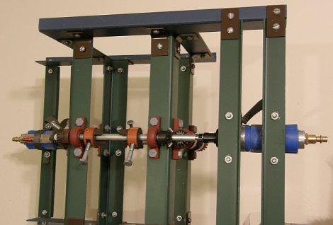
Third model, with 10,000 rpm ele. motors

The only expensive parts are the motors, (aluminum) pillow blocks, and mitre gears.
The pillow blocks, and mitre gears, combined, totalled $138.44. About a 2 foot square sheet of aluminum was less than $10. The shafts are also aluminum and cheap.
The shafts and pillow blocks are also, now, aluminum alloy. This model was fine but, the frame was just a little flimsy.

Note: I used the red/orange (Lovejoy) jaw couplings because they were a cheap easy way to attach weights on a shaft. I just replaced the set-screws with bolts. For a good close-up, click on the photo above (the 3 photos) to see an enlargement.
Experimenting out in the back yard, 1993

here I and a friend discovered the frame flexed a little

Final design: January 1994
using .090 inch aircraft aluminum ($9)
and 2 22,000rpm air motors ($50)

the frame is rigid and the motors are very light weight
I made the frame taller to accommodate longer arms and, slower speed requirements but, that was not necessary. However, there is an increased strength and reduced stress benefit to the double arms.
photographed on Fri., March 24th, 2006

Oct. 20th, 2007:
A few weeks ago +/- I tried it without any crossbars but, the weight and inertia were still too much for the motors. we got maybe 200 rpm but, we need maybe 600 to 800 rpm? I think the air pump where I am trying it, is not as strong as the one I used in Phoenix.
Nov. 2007:
I bought 2.5″ bolts and 1.5″ bolts so I have 2 more options. If the 2.5″ does not reduce the weight and inertia enough to enable the motors to get up some significant speed, I can try the 1.5″ bolts.
Cutting the length, and weight, in about half (from 4.75″ to 2.5″ bolts) reduces our net radius from about .1″ to about .025″ and our needed speed from about 600+ rpm to about 1200 rpm. Although it was an improvement, It just was not enough improvement and we switched to the 1.5 inchers. (see “December 2007” photo below) We started it up and the speed finally seemed significantly improved. A mechanic said it looked like it was going about 5 or 6,000 rpm. Great! Finally! Still, nothing more happened and we turned it off.
(we have no way of confirming how fast it was going – I think maybe only 1 or 2,000 rpm)
December 2007
Afterwards, I realized several potential problems. (1. The force may have been exerted downward instead of up (we need to try turning it upside down) and, (2. the 2 air hoses were adding weight to the system, holding it down. We need to prop the hoses up so that they do not add weight to the system.
Jan. 30th 2008:
We tried it again, right side up and upside down. We held up the 2 air hoses. But, no movement, no lift. It may be that we need 3-4000 rpm but are only getting 1 or 2000.
Testing at an auto body shop, Jan 30th 2008
 |
 |
June 30th 2008
If we got several thousand rpm, enough(?), then, it didn’t work. If not, then either a further reduction in the mass and inertia of the rotating weights and / or a change to stronger motors is needed.
Hopefully, we can get a sufficient speed increase by further reducing the weights & inertia. If not that, then by getting the weight of the motors off the frame by using couplers to extend the 2 shafts out beyond the frame.
March, 2009
I started getting calls from a TV production co. in Calif. wanting to put my flying machine on a Discovery Channel special.
I stopped at the auto shop, told them about it. They told me that they have gotten a new, stronger, compressor. Now is the time to try again!
Saturday, March 21st, 2009
Saturday was a disappointment. The new compressor provided significantly more power than the old one. The speed was much improved, very impressive, “more than enough”. This time I do think it was up to 3 or 4000 rpm, if not more. However, the weather was bad, raining, and I only did half the test. Still, it did not move. There was plenty of speed in the rotating masses. So, either I had it upside down, 50-50 chance of that being true, since it is totally symmetrical, or there is some stumbling block, some criteria I have not thought of.
Wednesday, July 22nd, 2009, 9am
Tried it again. The speed, again, seemed enough. But, again, I can’t be sure, and it did not go up.

2011, Footnote:
A frame is cheap, a person can design and build one around motors they come up with, the smaller the better, perhaps. Smaller motors can generally run at higher speeds. Extension rods, longer rods, can be used to get the motors off the system, and that will reduce the total weight greatly.
Here is one Marcelo B. built. Glad to hear from him.
back to Tesla’s Flying Machine, page 1
I have Autocad LT 2007 and was going to draft up something for your consideration. Before doing so I wanted to see if there were physical limitations. If your file can be converted or just sent in Autocad format, I can work with your drawing first.
I’m a semi-retired civil engineer ( bio at http://www.rw2LLC.com ) and my background in dynamics is more than rusty, but I believe we can significantly increase the radius of IL CoM, and reap whatever benefits we can from that. I also would suggest setting the unit on it’s side, on a wheeled device to see if we can get lateral movement.
Consider on your diagram, looking at the device in plan view as it’s drawn, north being at the top where the weight is extended away from the center of the device. Now consider the arm for that weight being long enough to extend the weight to rotate almost to the cross bar at the south end. The south end bar has TWO weights, each approx half the weight of the north weight. These are situated equi-distance from the north/south centerline. The arms for the south would be (volumetrically) about half of the north. Basically just to make the two weights (and the forces due to wind resistance) maintain the same center of gravity (terminology?) as the single north arm, but of course in opposition. Likewise one east/west arm is long, and the opposite side has two “half” weights, thereby allowing the weights to occupy nearly the entire inside space.
Just drawing this and confirming the track of IL CoM and the possibility that this physically can operate would be enough for me at this moment, but, I pose a couple other possible ideas.
1. Having this attached on it’s side, to a “sled” of sorts, we are attempting to generate the linear motion along the horizontal path. Would multiple units, each generating the same linear force, operate in an additive fashion? Say 4 units all set to develop a linear force along the same horizontal direction?
2. By using fewer motors, running say 4 units from 2 or 4 motors, weight may be reduced, but here is the other thought. Although all units are rotating the weights in the same way and same speed, “tune” or “set” the weights to work against each other. Setting 2 units by 2 units, “mirror” the horizontal weights so they are opposite each other. Likewise for the weight spinning vertically. The vibration horizontally would cancel as well as the vertical. Obviously I am not suggesting building 4 units now, although I am curious about your thoughts on my ideas.
I am impressed with your physical work on the device though, and hope perhaps I can help with some other ideas.
Rick Warden
PS I got to thinking about the configuration and wonder, if 4 LONG arms would even collide? Perhaps I’m missing something without drawing it. If that could be a possible configuration, would the centers of gravity and the resulting motion make a better device?
I was thinking how nice it would be if we knew how Tesla transmitted his energy to his “receiver” as in Wardenclyffe (sp?). No cord necessary!
I believe I used turbocad back in the early 90’s but have long since lost the original file(s) and only have scanned printouts now.
Watch the movement on motor in motion and see that they never cross paths. Alternating 1 & 2 weights is not necessary.
I did try setting it horizontal, long ago but, realized it is like magnets approaching each other. Only the distance matters, not the direction, up down or sideways. The forces here are much greater than gravity, even greater than magnetism.
There are “economies of scale” and cost: Build the smallest possible with motors that are just barely “up to the task”? – the smallest lightest-weight possible motors that can still do the job for only the shortest amount of time? Your 2 or 4 units ideas are valid but introduce more complex issues that may be counter-productive. Someone could try it.
I am hoping that by cutting the weight of the masses in half, I will more than quadruple the speed the motors can generate. I have already gone from 0 to at least a thousand rpm, maybe more. Reducing the weight by half only increases the required speed by about 1.3 “economy of scale”